Binary adder and parallel adder Full-adder circuit, the schematic diagram and how it works – deeptronic Adder bit subtractor circuit ripple carry diagram logic using project build only digital computing learn let its single indie electronics
Design and explain 8 bit binary adder using IC 7483.
Design and explain 8 bit binary adder using ic 7483. 8 bit adder circuit Adder logic binary circuit gates diagram using array make inputs labeled twice below also used
Adder additionneur binaire zpag electroniques gate sum
Adder subtractor logic add sub combinational circuits bit binary using subtraction tutorial adders electronics6.4: 2-bit adder circuit Combinational and sequential design of a 4-bit adder. (a) ha circuitAdder logic bit four diagram boolean half two simple adders answer so now.
Adder circuit diagram schematic bit works figureBoolean algebra Binary adder and parallel adderAdder bit logic implementation circuit half adders numbers electronics diagram two bits carry schematic ripple digital add build implement together.

Adder vhdl 8bit compile simulate waveform verify
Adder adders libretexts circuits pageindexAdder bit circuit half make logic diagram comparator gates first electronics questions cout second there only puzzle solved connecting which A binary adder made using and-or array logicBinary arithmetic circuits.
Adder subtractor binary circuit bit diagram coa logic block javatpoint modeAlex9ufo 聰明人求知心切: verilog 4-bit binary adder-subtractor Adder diagram binary additionAdder binary multisim.

Adder bit gates nand implementation diagram only add
Adder binary parallel bit circuit adders carry bits addition cpu calculate hardware level does unit say same would these stackLet's learn computing: 4 bit adder/subtractor circuit Adder bit circuitBinary adder/subtractor.
What is parallel binary adder?N-bit binary adder circuit by logisim Vhdl tutorial – 21: designing an 8-bit, full-adder circuit using vhdlSolved 1. the figure above shows a 4-bit bcd adder. you can.

Adder truth logic half sumador gates binario inputs datasheet combination suma microcontrollerslab
Digital logic design: binary parallel adder/subtractorAdder subtractor bit make carry ripple verilog binary using 4bit want two subtraction numbers addition input operation control output has Tech2play: binary additionAdder kindpng.
Adder combinational sequentialThe answer is 42!!: four bit full adder tutorial 😊 four bit parallel adder. 4 bit binary adder circuit / block diagramBinary adder circuit / circuit additionneur binaire.

Logic adder subtractor parallel binary circuit bit diagram control signal mode digital determines which has
Adder bit parallel four circuit binary diagram logic subtractor digital block example geeksforgeeks detailed discussionAdder parallel binary serial bits gif taken stack Adder logisim bit circuit binaryBinary adder.
8 bit adder circuit diagram, hd png downloadBit adder subtractor complement binary arithmetic add twos digital circuits sub overflow electronics detection fig learnabout Logic gatesFull adder circuit: theory, truth table & construction.

Adder bit ic 7483 using binary parallel adders four explain ques10
Adder bcd bit binary two diagram logic block adders combinational figure chegg answer shows solved has help2-bit adder implementation Adder circuit construction binary circuits ibm sourav guptaCd4008 4-bit full adder ic pinout, working, example and datasheet.
Adder binary parallel bit logic diagram circuit electronics between .


tech2play: Binary Addition

Design and explain 8 bit binary adder using IC 7483.

Full-Adder Circuit, The Schematic Diagram and How It Works – Deeptronic

Let's Learn Computing: 4 bit Adder/Subtractor Circuit
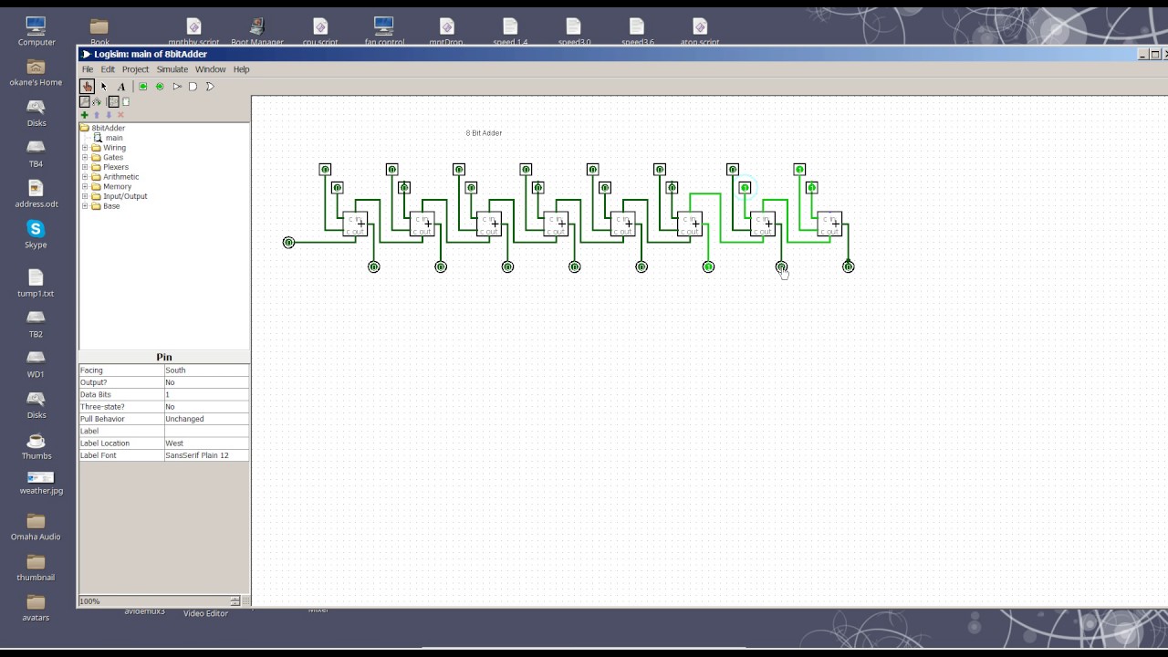
8 Bit Adder circuit - YouTube

logic gates - How to make 2 bit or more half adder circuit - Electrical
