Vhdl tutorial – 21: designing an 8-bit, full-adder circuit using vhdl Circuit adder bit diagram logic computing learn let 3 bit full adder
Adder - Classifications, Construction, How it Works and Applications
8 bit adder circuit Adder logic half boolean implementation Adder fitfab
Adder logic binary circuit gates diagram using array make inputs labeled twice below also used
Adder subtractor bit circuit add sub questions overflow complement logic detection carry addition designing control zero line digital findFull adder circuit diagram Digital logicFitfab: eight bit 8 bit adder truth table.
Adder bcd bit binary two diagram logic block adders combinational figure chegg answer shows solved has help😊 four bit parallel adder. 4 bit binary adder circuit / block diagram Adder theorycircuitAdder circuit construction binary circuits ibm sourav gupta.

Design and explain 8 bit binary adder using ic 7483.
Solved 1. the figure above shows a 4-bit bcd adder. you canAdder adders libretexts circuits pageindex Adder bit parallel four circuit binary diagram logic subtractor digital block example geeksforgeeks detailed discussionCircuit diagram of a one-bit full adder using the proposed technique in.
Full adder logic diagramLet's learn computing: 4 bit adder circuit Block diagram of an 8-bit adder (32-bit adder is essentially the sameAdder half truth schematic circuitglobe circuits representation robhosking xor sum edupointbd.

Adder kindpng
Logic diagram for 8 bit adder6.4: 2-bit adder circuit Adder bit using circuit adders half four circuits implementation watson single just box latech eduAdder cmos soi.
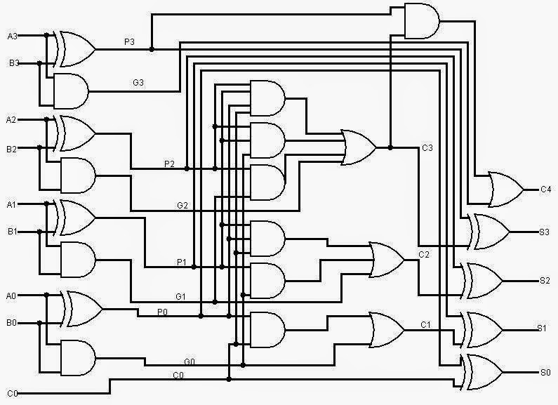
Adder bit carry logic diagram verilog look digital ahead collaborative learning arithmetic circuits hdl binary figure lookahead generator four nameLogic gates Adder logic wiring calculatorsFull adder circuit: theory, truth table & construction.

Adder binary logic stack adders circuits implement options
8 bit adder circuit diagram, hd png downloadAlu diagram block adder mini bit introduction figure final Adder truth logic half sumador gates binario inputs datasheet combination suma microcontrollerslabAdder bit essentially.
Adder bit ic 7483 using binary parallel adders four explainAdder vhdl 8bit compile simulate waveform verify Full adder logic diagram and truth table : what is a 2-bit full adderAdder half bit circuit make two adders logic gates electronics description combined happened has.

Cd4008 4-bit full adder ic pinout, working, example and datasheet
Adder bit circuitA binary adder made using and-or array logic .
.

Logic Diagram For 8 Bit Adder - Wiring Diagram

Watson

CD4008 4-Bit Full ADDER IC pinout, working, example and datasheet

digital logic - Designing a 4-bit adder-subtractor circuit - Electrical

Adder - Classifications, Construction, How it Works and Applications

Fitfab: Eight Bit 8 Bit Adder Truth Table

Full Adder Circuit: Theory, Truth Table & Construction
